THEORY of Indication for insulation failure point
As shown on the drawing 2, considering that an insulation failure (Rx) happens between solar panel modules and provided that the generated voltage of PV system is Vo and the voltage from insulation failure point to P phase terminal is Vx. Also, provided that applied voltage is V1 and current is I1.
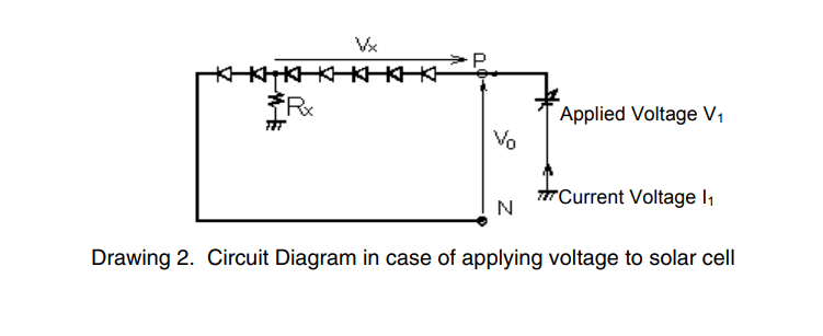
When measuring the insulation resistance two times by changing voltage, provided that the fist applied voltage is V1, current I1 and the second applied voltage is V2, current I2, the drawing 3 is showing the relation between these applied voltages and currents.
The intersection point Vx with horizontal axis (current I=0) on the drawing 3 is showing the generated voltage of solar panel from P phase to the insulation failure point. The insulation failure point can be specified by the ratio of the generated voltage of solar panel Vo to the generated voltage to failure point Vx

MIS-PV1

PV OK, 2 RANGE
FEATURES
- Can measure accurately during PV generating
- Safety – no need to short-circuit P & N phase
- Measurable from AC circuit to PV panels
- Switchover 2 ranges – 500/1000V
MIS-PV2

PV OK, 4 RANGE, AC VOLT
FEATURES
- Can measure accurately during PV generating
- Safety – no need to short-circuit P & N phase
- Measurable from low voltage circuit to PV panels
- Can be used in ordinary electric circuit
- Switchover 4 ranges – 125/250/500/1000V
MIS-PVS
PV OK, 2 RANGE, DC VOLT, DETERIO RATION
FEATURES
- With function to judge deterioration point (only for solar panel measurement)
- Can measure accurately during PV generation
- Safety – no need to short-circuit P & N phase
- Measurable from AC circuit to PV panels
- Measurable generated voltage (DC0〜999V)
- Switchover 2 ranges – 500/1000V
GENERAL
We developed the insulation resistance tester which can measure insulation resistance at solar panels easily under generating condition. (Patent Pending).
The ordinary insulation resistance testers cannot measure resistance correctly during generation but model MIS-PVS can make measurement easily regardless of generating or no power and also can display the insulation failure point. (at P phase side, N phase side or between modules).
(1) Indicate the insulation failure point of PV systems
(2) Can measure the insulation resistance at solar panel side under generating conditions by one operation.
(3) Can measure the insulation resistance of ordinary electrical equipment.
MEASUREMENT
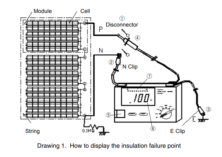
- Make the disconnector off.
- Apply N clip of the tester to N phase side.
- Connect E clip to grounding earth side.
- Apply the probe to P phase side of solar panel.
- Set the measuring switch of MIS-PVS on.
- The insulation resistance value is displayed on LCD.
- In case of the measured value less than 1MΩ, P1~P12 on LCD display will be lightening. When P3 is lightening, there is an insulation failure at the place between 3/10 and 4/10 of whole modules. P1 will be lightening in case of the insulation failure at P phase side and P11 will be lightening in case of failure at N phase side.
SPECIFICATIONS
| EFFECTIVE RATED VOLTAGE | MIS-PV1/MIS-PVS(500/1000V) MIS-PV2(125/250/500/1000v) | |||
| 125V | 250V | 500V | 1000V | |
| MAXIMUM DISPLAY | 20MΩ | 50MΩ | 100MΩ | 200MΩ |
| CENTER | 0.5MΩ | 1MΩ | 2MΩ | 50MΩ |
| FIRST EFFECTIVE | 0.02MΩ〜10MΩ | 0.05MΩ〜20MΩ | 0.1MΩ〜50MΩ | 2MΩ〜1000MΩ |
| TOLERANCE | Less than ±5% | |||
| SECOND EFFECTIVE | 0.01MΩ〜less 0.02MΩ Over 10MΩ〜20MΩ |
0.02MΩ〜less 0.05MΩ Over 20MΩ〜50MΩ |
0.05MΩ〜less 0.1MΩ Over 50MΩ〜100MΩ |
1MΩ〜less 2MΩ Over 1000MΩ〜2000MΩ |
| TOLERANCE | Less than ±10% | |||
| DETERIORATION (ONLY MIS-PVS) |
Deterioration point will be displayed on LCD in case of insulation resistance less than 1MΩ. ※Only during measurement of PV panels, indicate P or N phase and or between modules. |
|||
AC VOLTAGE(ONLY MIS-PV2)
| RANGE | AC0〜599V (Min. Resolution 0.1V) |
| TOLERANCE | ±1.5%rdg±10dgt |
DC VOLTAGE(ONLY MIS-PVS)
| RANGE | DC0〜999V (Min. Resolution 0.1V) |
| TOLERANCE | ±1.5%rdg±10dgt |
GENERAL
| DISPLAY RANGE | 3.200MΩ/32.00MΩ/320.0MΩ/3200MΩ (4 Range Auto) |
| OTHER FUNCTIONS | OVER RANGE DISPLAY, DATA HOLD, AUTO POWER OFF, BACKLIGHT, LOW BATTERY DISPLAY, AUTO DISCHARGE |
| STANDARD | JIS C 1302 Equivalent |
| OPERATING TEMPERATURE | 0〜40℃, less than 80%RH (without condensing) |
| POWER SUPPLY | 1.5V (AA size, LR6) alkali battery×6 pcs. |
| DIMENSION/WEIGHT | 170(W)×105(D)×52(H)㎜, approx. 350g (without batteries) |
| ACCESSORIES | MIS-PV1 : Line Cord×1, Earth Cord×1, Case for Cords MIS-PV2 : Line Cord×1, Earth Cord×1, Hard Case for Instrument×1 MIS-PVS : Line Cord×2, Earth Cord×1, Hard Case for Instrument×1 Common : Insulation Cap×1, Belt×1, LR6 battery×6, Instruction Manual×1 |