LID – UPD
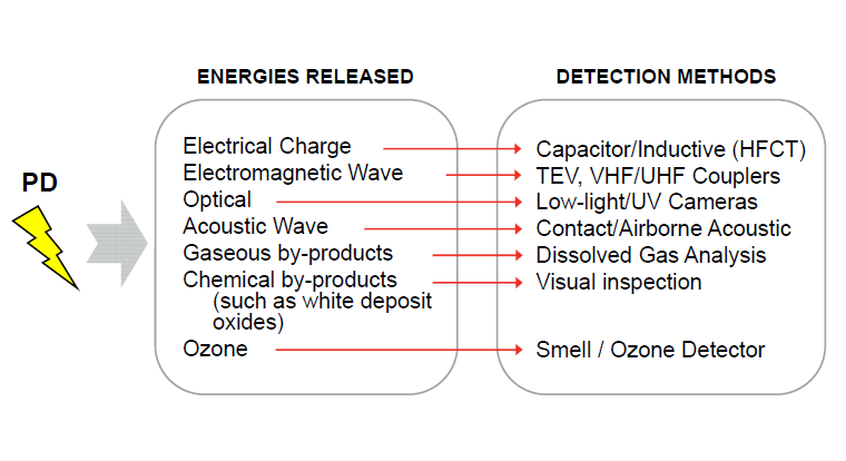
Introduction: PD is an electrical discharge that occurs across a localized area of the insulation between two conducting electrodes, without completely bridging the gap (see IEC 60270). It can be caused by discontinuities or imperfections in the insulation system. PD activity is an indication of an incipient medium voltage (MV) or high voltage (HV) insulation fault and is widely regarded as the best early warning indicator of electrical insulation deterioration in MV and HV electrical assets
Partial Discharge: : Partial Discharge testing and monitoring is particularly important when the medium or high voltage asset is critical to the operation of a network; this may be due to the asset’s age, limited network redundancy, past failures or the financial consequences of a failure. Examples of MV and HV plant that can be tested/monitored include:
- Cables and cable accessories (terminations, joints, sealing ends)
- Switchgear (AIS, SIS & GIS)
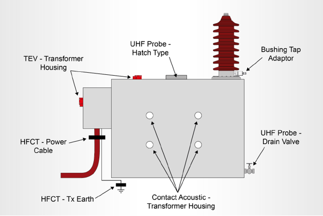
- Power Transformers and Bushings
- Transformers (Oil Filled & Dry Type)
- Instrument Transformers (Voltage & Current)
- Capacitors
Features
- Measurement of Leakage Current provide prior Information about the healthiness of the Transformer & Other substation equipment
- Since no labour is required to perform the tests, continuous monitoring allows the use of limited resources to find solutions to problems instead of finding problems.
- Reducing unnecessary maintenance because the monitor will be constantly testing and will have accurate data on which to base decisions.
- No introduction of infant mortality failure patterns via more invasive testing procedures.
- Reduction of forced outages and increased safety of personnel. One will always be aware of conditions and/or problems.
- Easily monitor worsening conditions so one can defer repairs and allow time to plan an outage.
Technical Specifications
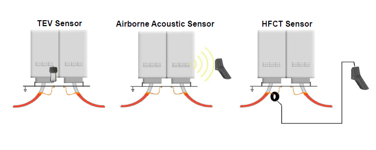
- TEV Sensor
- Measurement Range (Peak) 0 – 70 dBmV
- Measurement Range
- (Cumulative Activity) 0 – 350,000 mV/cycle
- Frequency Response 5 – 60 MHz
- Resolution 1 dB
- Accuracy ±1 dB
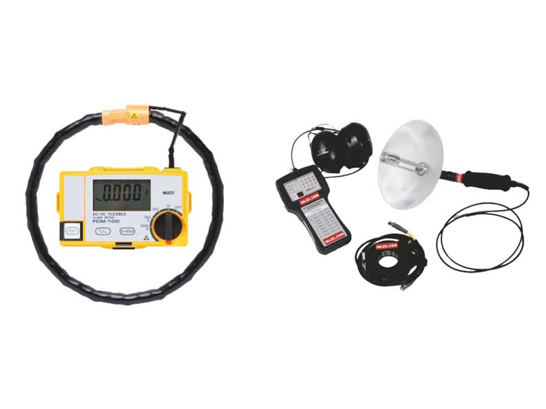
- HFCT Sensor
- Measurement Range
- (HFCT 100/50, Ztr=3.9) 200 pC/cycle – 20,000 nC/cycle
- Frequency Response(-3 dB response) 100 kHz – 20 MHz
- Resolution 1 dB
- Accuracy ±1 dB
- Flexible CT Leakage Current Tester
- Flexible Split-Core within built shielding
- AC & DC Leakage/Line Current
- Single CT with Dual Integration Mode
- AC & DC 3A/30A/300A/3000A (AC50/60 Hz & DC)
- ±3% of reading