Ior (RESISTIVE) LEKAGE CURRENT MEASUREMENT
BACKGROUND
Nowadays, many harmonics and high-frequency current are contained to leakage current of grounding line and or other circuits due to spread of high-frequency electric apparatus with inverter, converter, etc. and the measured values by different instruments are not same even at the same measuring point.
Generally, leakage current contains the resistive component (Ior) which flows to the ground by insulation deterioration and also, the capacitive component (Ioc) which flows by electrostatic capacity caused from above high-frequency and harmonics.
The actual insulation deterioration should be related with only Ior but ordinary leakage clamp testers can measure only Io (vector between Ior & Ioc as under drawings) and cannot judge what kind of leakage current is flowing.

MEASURING METHODS FOR RESISTIVE LEKAGE CURRENT
There are mainly two methods for measuring resistive component of leakage current as followings:
1. Igr Method – Inputting a certain fixed low range frequency to the circuit by injection CT.
2. Ior Method – Measuring synchronous current based on the circuit voltage inputted to clamp tester.

We are adopting Ior method to all our Io/Ior Digital Clamp Testers (except for model MCL-400IR), as Igr method is very difficult to have injection CT in the actual measuring fields.
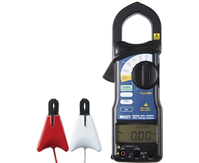
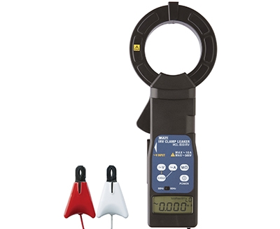
Our new models MCL-500IRV, 340IRV & MCL-800IRV have non-contact voltage sensors which enable more safely measurement without touching voltage terminals.
Also, model MCL-400IR has very unique method, detecting harmonics (5th & 7th) and measuring resistive component by calculations without voltage input.
M-340IRV

Mini Type, easy to hand carry
FEATURES
Integrated Non-contact Voltage Input Type Clamp Leaker.
*Safety: Available voltage input from the coated conductors (not touching voltage terminal)
*Convenience: Built-in LCD display combined with clamp CT.
It is getting more & more difficult to check the insulation conditions by ordinary Io leakage current due to spread of inverter appliances, etc.
By detecting resistive leakage current (Ior), management of insulation conditions can be made more accurately on the live lines
MCL-500IRV

Wide Range, measurable from mA to Line Current up to 500A
FEATURES
Integrated Non-contact Voltage Input Type Clamp Leaker.
*Safety: Available voltage input from the coated conductors (not touching voltage terminal)
*Convenience: Built-in LCD display combined with clamp CT.
It is getting more & more difficult to check the insulation conditions by ordinary Io leakage current due to spread of inverter appliances, etc.
By detecting resistive leakage current (Ior), management of insulation conditions can be made more accurately on the live lines
MCL-800IRV

Big Window CT, High Precision
FEATURES
Integrated Non-contact Voltage Input Type Clamp Leaker.
*Safety: Available voltage input from the coated conductors (not touching voltage terminal)
*Convenience: Built-in LCD display combined with clamp CT.
It is getting more & more difficult to check the insulation conditions by ordinary Io leakage current due to spread of inverter appliances, etc.
By detecting resistive leakage current (Ior), management of insulation conditions can be made more accurately on the live lines
MCL-400IR

FEATURES
- Can measure the resistive leakage current (Ior) of the grounding lines and other electric circuit without voltage input.
Specifications
| Parameters | M-340IRV | MCL-500IRV | MCL-800IRV | MCL-400IRV |
|---|---|---|---|---|
| Measuring Function | Line Current Leakage Current Resistive Leakage Current | Line Current Leakage Current Resistive Leakage Current | Line Current Leakage Current Resistive Leakage Current | Line Current Leakage Current Resistive Leakage Current Harmonics current and voltage (Fundamental, 3rd, 5th,7th, 11th and 13th) AC Voltage |
| Available Circuits for Ior Measurement | 1P/2W, 1P/3W, 3P/3W | 1P/2W, 1P/3W, 3P/3W, 3P/4W star connection | 1P/2W, 1P/3W, 3P/3W, 3P/4W star connection | |
| CT Inside Diameter | φ40mm | φ40mm | φ80mm | φ40mm |
| AC Current Range | 10mA/100mA/60A | 40mA/400mA/4A/40A/500A | 10mA/100mA/1000mA/10A | AC 0-40mA, 400mA, 4A, 40A, 300A, AC 0~500V |
| Minimum Resolution | 0.001mA | 0.01mA | 0.001mA | 0.01mA |
| Accuracy | Range/ Resolution/ Accuracy I 60A/ 0.01A/ 0 ~ 49.99A ±1.0%rdg±10dgt 50A ~ 59.99A ±3.0%rdg±10dgt Io 10mA/ 0.001mA/ ±1.0%rdg±10dgt 100mA/ 0.01mA/ ±1.0%rdg±10dgt Ior 10mA/ 0.001mA/ ±3.0%rdg±20dgt 100mA/ 0.01mA/ ±2.5%rdg±20dgt | Range/ Resolution/ Accuracy I, Io 40mA/ 0.01mA/ ±1.0%rdg±10dgt 400mA/ 0.1mA/ ±1.0%rdg±10dgt 4A/ 0.001A/ ±1.0%rdg±10dgt 40A/ 0.01A/ ±1.0%rdg±10dgt 500A/ 0.1A/ ±1.0%rdg±3.0%FS Ior(direct) 40mA/ 0.01mA/ ±1.5%rdg±15dgt 400mA/ 0.1mA/ ±1.2%rdg±15dgt 4A/ 0.001A/ ±1.2%rdg±15dgt Ior (non- contact) 40mA/ 0.01mA/ 0.40mA~3.99mA/ ±3.0%rdg±20dgt 4.00mA~39.99mA/ ±1.5%rdg±15dgt 400mA/ 0.1mA/ 4.0mA~39.9mA/ ±3.0%rdg±20dgt 40.0mA~399.9mA/ ±1.5%rdg±15dgt 4A/ 0.001A/ 0.040A~0.399A/ ±3.0%rdg±20dgt 0.400A~3.999A/ ±1.5%rdg±15dgt Voltage 500V/ 0.1V/ ±1.0%rdg±8dgt | Range Resolution Display Accuracy I, Io 10mA/ 0.001mA/ ±1.0%rdg±10dgt 100mA/ 0.01mA/ 1±1.0%rdg±10dgt 1000mA/ 0.1mA/ ±1.0%rdg±10dgt 10A/ 0.001A/ ±1.0%rdg±10dgt Ior (direct) 10mA/ 0.001mA/ ±1.5%rdg±20dgt 100mA/ 0.01mA/ ±1.5%rdg±15dgt 1000mA/ 0.1mA/ ±1.5%rdg±15dgt 10A/ 0.001A/ ±1.5%rdg±15dgt Ior (non contact) Single Phase 10mA/ 0.001mA/ ±2.0%rdg±20dgt 100mA/ 0.01mA/ ±2.0%rdg±15dgt 1000mA/ 0.1mA/ ±2.0%rdg±15dgt 10A/ 0.001A/ ±2.0%rdg±15dgt Ior (non contact) Three Phase 10mA/ 0.001mA/ 0.500mA~4.999mA ±3.0%rdg±40dgt 5.000mA~9.999mA ±2.0%rdg±15dgt 100mA/ 0.01mA/ ±2.0%rdg±15dgt 1000mA/ 0.1mA/ ±2.0%rdg±15dgt 10A/ 0.001A/ ±2.0%rdg±15dgt Voltage 500V/ 0.1V/ ±1.0%rdg±8dgt | Measuring Function/Range/Resolution/Accuracy AC Current/40mA/0.01mA/±1.0%rdg±8dgt AC Current/400mA/0.1mA/±1.0%rdg±8dgt AC Current/4A/0.001A/±1.0%rdg±8dgt AC Current/40A/0.01A/±1.0%rdg±8dgt AC Current/300A/0.1A/±1.0%rdg±1%FS AC Voltage/500V/0.1V/±1.0%rdg±8dgt Fundamental, 3rd, 5th, 7th : 1%rdg±5dgt±AC current and voltage accuracy 11th and 13th Harmonics : 2%rdg±5dgt±AC current and voltage accuracy (Min. fundamental input current : more than 2% of each current) |
| Display | LCD, max.9999 reading with annunciator | LCD, max.9999 reading with annunciator | LCD, max.9999 reading with annunciator | 3.5 digit LCD, max. reading of 4000 |
| AC Conversion | Successive approximation method | Successive approximation method | Successive approximation method | Average sensing rms reading |
| Input Frequency | 45~65Hz (by switch for 50/60Hz) | 50/60Hz ( Auto) | 50/60Hz (manual change) | 45-65Hz |
| Measuring method | Clamp CT (in case of Ior, based on voltage standard) | Clamp CT (in case of Ior, based on voltage standard to be inputted directly or by non-contact voltage sensor | Clamp CT (in case of Ior, based on voltage standard to be inputted directly or by non-contact voltage sensor | Dual slope integration mode |
| Over range indication | "OL" mark on LCD | "OL" mark on LCD | "OL" mark on LCD | "OL" mark on LCD |
| Low battery indication | "Battery mark" on LCD | "Battery mark" on LCD | "Battery mark" on LCD | "Battery mark" on LCD |
| Auto power off function | Approx. 10 minutes later after final key operation | Approx. 10 minutes later after final key operation | Approx. 10 minutes later after final key operation | Approx. 10 minutes later after final key operation |
| Data hold indication | "DH" mark on LCD | "DH" mark on LCD | "DH" mark on LCD | "DH" mark on LCD |
| Sampling Rate | Two Times/Second | Two Times/Second | Two Times/Second | Two Times/Second |
| Operating Circuit Voltage | Less than AC500V (Isolated Electric Wire) | Less than AC500V (Isolated Electric Wire) | Less than AC500V (Isolated Electric Wire) | Less than AC 500V |
| Withstanding Voltage | AC 2200V/1 minute between CT core and grip | AC 2200V/1 minute between CT core and grip | AC 2200V/1 minute between CT core and grip | AC 2200V, 1minute |
| Influence of external magnetic field | Less than 5mA (nearby 100A conductor) | |||
| Operating Temp. & Humidity Range | 0~50℃ Less than 85%RH (w/o condensation) | 0~50℃ Less than 85%RH (w/o condensation) | 0~50℃ Less than 85%RH (w/o condensation) | 0℃~40℃, < 80%RH ( Without condensation ) |
| Storage Temperature | -10~60℃, < 80%RH (without condensation) | -10~60℃, < 80%RH (without condensation) | -10~60℃, < 80%RH (without condensation) | -10~60℃, < 70%RH (without condensation) |
| Power Supply | AAA Size Alkaline Battery x 3 | AAA Size Alkaline Battery x 3 | AAA Size Alkaline Battery x 3 | 1.5V ("AAA" sixe, um-4)x3 or AC adaptor (Option) |
| Power consumption | 10mA (approx. 80h for continuous use) | 13mA (approx. 48h for continuous use) | 14mA (approx. 48h for continuous use) | Approx. 8mA (Approx. 60 hours continuous) |
| Dimension/Weight | W44×H197×D24mm Approx.210g | W70×H223×D34mm Approx.440g | W71×H315×D37mm Approx.750g | 70(W)x223(H)x34(D)mm Approx. 440g including batteries |
| Accessories | Carrying Case, Non-contact Voltage Sensor, Instruction Manual | Carrying Case, Non-contact Voltage Sensor, Direct Voltage Input Sensor, Instruction Manual | Carrying Case, Non-contact Voltage Sensor, Direct Voltage Input Sensor, Instruction Manual | Carrying Case…..1, Instruction Manual…..1 Batteries…..3 (installed into the instrument) |
| Dimension/Weight | W44×H197×D24mm Approx.210g | W70×H223×D34mm Approx.440g | W71×H315×D37mm Approx.750g | 70(W)x223(H)x34(D)mm Approx. 440g including batteries |

