MEASURING METHOD of MET-1/MET-2 Clamp Earth Tester
In the equivalent circuit, approx.160mV p-p (MET-1) or approx. 320mV p-p (MET-2) is injected from Injection CT by changing frequency from 4 KHz to 400 KHz (MET-1) or 4KHz to 200KHz (MET-2).Then, the resonance will happen by L & C0 or r & C1 in the circuit and the resonance current will flow. At the time of resonance, the current will be maximum.By detecting this resonance current, the current value at resonance point (IZ) and synchronous current at injected frequency can be calculated and the earth resistance can be displayed.At the time of resonance by L & C0, current I will flow as the above route and can measure Re (Earth Resistance).

At the time of resonance by L & C0, current I will flow as the above route and can measure Re (Earth Resistance).
*Cannot measure the resistance in no-looping circuit like as grounding line connected with lightening rod but can get the value by
connecting with other grounding lines, using the subsidiary lead wire.
Application Example
1. Measurements for the active line
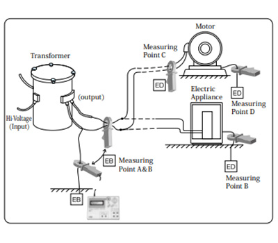
The earth resistance can be measured by clamping 2 CTs near at transformer (point A or B) and near at the electrical loading part (motor, electric appliance, etc.)
2. Electric installation
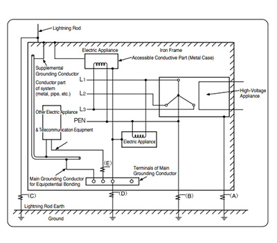
“ sigma” shows the clamping point of the injection CT and the measuring CT.
3. Earth resistance measurements for telecommunication
system
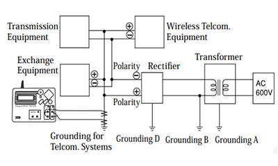
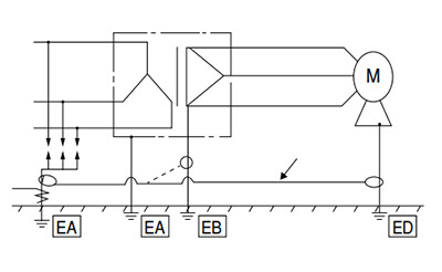
4. Measurements where L (inductance) & C (capacitance) are
low
Where L & C resonance has not been gotten, this instrument may show “OVER” at the display. In this case, connect the objective grounding line (EA) to other grounding lines (EB or ED) by the subsidiary lead wire and clamp 2 CTs at the measuring point (EA). Even in the case of no resonance between L & C, the multiple earth resistance can be measured.
MET-1
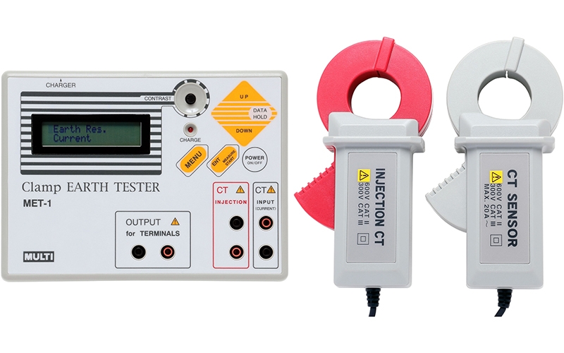
FEATURES
- Completely different method from the ordinary Earth Testers.
- Just clamping two CTs to the earthing conductor and no need to use auxiliary earth rod.
MET-2
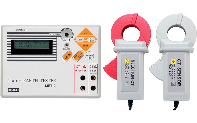
FEATURES
- Completely different method from the ordinary Earth Testers.
- Just clamping two CTs to the earthing conductor and no need to use auxiliary earth rod.
| SPECIFICATIONS | MULTI MET-1 | MULTI MET-2 | MULTI MET-10X |
| Measuring function | Earth Resistance, AC Current (Load and Leakage) | Earth Resistance AC Current (Load and Leakage) Surge impedance | |
| Accuracy(Earth resistance) | (23℃ ± 5℃, 85% RH or less) Range / Resolution / Accuracy 200Ω / 0.1Ω / 0 ~ 10Ω : ±0.2Ω, 200Ω / 0.1Ω / 10 ~ 50Ω : ±1.0Ω, 200Ω / 0.1Ω / 50 ~200Ω : ±5.0Ω | (23℃ ± 5℃, 85% RH or less) Range / Resolution / Accuracy 10Ω / 0.01Ω / 0.1~1Ω :±0.1Ω, 10Ω / 0.01Ω / 1~10Ω :±0.5Ω 300Ω / 0.1Ω / 10~50Ω :±2.0Ω, 300Ω / 0.1Ω / 50~150Ω: ±5.0Ω 300Ω / 0.1Ω / 150~200Ω :±20Ω, 300Ω / 0.1Ω / 200~300Ω :±30Ω | Range : Low Measurement range /Resolution/Accuracy : 0.10~1.00 Ω/0.01 Ω/±0.1 Ω 1.00~10.00 Ω/0.01 Ω/±0.5 ΩRange : High Measurement range/Resolution /Accuracy : 10.0~50.0 Ω/0.1 Ω/±2.0 Ω 50.0~200.0 Ω/0.1 Ω/±5.0 Ω 200.0~300.0 Ω/0.1 Ω/±20.0 Ω 300.0~500.0 Ω/0.1 Ω/±30.0 Ω |
| Accuracy(AC current) | (23℃ ± 5℃, 85% or less) Range/Resolution/Accuracy 200mA/0.1mA/3% rdg ± 8dgt 2000mA/1mA/2% rdg ± 8dgt 20A/0.01A/2% rdg ± 8dgt | (23℃ ± 5℃, 85% RH or less) Range/Resolution/Accuracy 200mA/0.1mA/3% rdg ± 8dgt 2000mA/1mA/2% rdg ± 8dgt 20A/0.01A/2% rdg ± 8dgt | Range /resolution/Accuracy 0.0~200 mA/0.1 mA/3 %rdg ±8 dgt 200~2000 mA/1 mA/ 2 %rdg ±8 dgt 2.00~20 A/ 0.01 A/2 %rdg ±8 dgt |
| Injection signal | Approx. 320mVp-p, Auto sweep 4KHz~400KHz | Approx. 160mVp-p, Auto sweep 4KHz~200kHz | Approx. 160 mVp-p, Auto sweep 4 kHz~200 kHz |
| Measuring time | Approx. 30 second for earth resistance | – | |
| Measuring CT | φ34mm with 2.5m lead | φ34/φ80 mm with 2.5 m lead | |
| Injection CT | φ34mm with 2.5m lead | φ34/φ80 mm with 2.5 m lead | |
| Safety standard | IEC 61010-1, IEC61010-2-032 Installation CAT II 600V or CATⅢ 300V | – | |
| Display | LCD, 16 letters/characters × 2 lines with contrast adjuster | LCD, 16 letters/characters × 2 lines with contrast adjuster | |
| A/D Conversion | Dual slope integration mode | Dual slope integration mode | |
| Sampling | Approx. 2 times/sec. for AC current | Approx. 2 times/1 sec. for AC current | |
| Memory function | – | 200 measuring data can be stored and displayed | 200 measuring data can be stored and displayed |
| Communication | Bluetooth4.2 Class2 | ||
| Auto power off function | Approx. 5 minutes after power on | Approx. 10 min. after the last button operation | |
| Over range indication | “OVER” on LCD | “OVER” on LCD | |
| Data hold indication | “DH” mark on LCD | “DH” mark on LCD | |
| Low battery indication | “B” mark on LCD | Battery mark on LCD | |
| Limitation of circuit voltage | Less than 600V | Less than 500V | Less than 500V |
| Withstanding Voltage | AC 3700V, 1 minute( between CT core and CT handle) | AC 3700 V, 1 min. (between CT core and CT handle) | |
| Insulation Resistance | More than 100MΩ (between CT core and CT handle) | More than 100 MΩ by 500 V insulation resistance tester (between CT core and CT handle) | |
| Operating Temperature | 0℃~40℃, < 85%RH ( without condensation) | 0℃~40℃, < 85%RH ( without condensation) | |
| Storage Temperature | -10℃~60℃, < 80% (without condensation) | -10℃~60℃, < 80% (without condensation) | |
| Size and Weight | Measuring CT:90.5(W)×165(H)×38(D)mm, approx.460g Injection CT:90.5(W)×165(H)×38(D)mm, approx.440g Main unit:190(W)×140(H)×42 (D)mm, approx.800g | Main unit : 190(W)×140(H)×42 (D) mm, approx. 450 g Measuring : Φ34 mm CT : 90.5(W)×165(H)×38(D) mm, approx. 460 g Φ80 mm CT : 125(W)×240(H)×40(D) mm, approx. 570 g Injection: Φ34 mm CT : 90.5(W)×165(H)×38(D) mm, approx. 440 g Φ80 mm CT : 125(W)×240(H)×40(D) mm, approx. 670 gOptional shielded reinforcement:123(W)×120(H)×42(D) mm, approx. 220 gAttention : The injection Φ80 mm CT and the measuring Φ80 mm CT should be isolated distance between around 80 cm, but if can not be kept apart this distance, the injection Φ80 mm CT has to install the optional shielded reinforcement. | |
| Battery life | 450 times measurements under full charged condition (Subject to the times of charging and discharging) | Approx.400 times measurements under full charged condition (Subject to the times of charging and discharging) | |
| Battery charger | AC200V~240V (50/60Hz) | ||
| Power supply | NiMH battery pack (1.2V x 5) | AA alkaline battery LR6×4 AC adapter (US type) | |
| Power Consumption | Approx. 160 mA When battery voltage 6 V (Earth resistance measurement) | ||
| Accessories | Measuring CT: 1 Injection CT: 1 Battery charger: 1 Carrying case: 1 Subsidiary lead wire:1 (Optional in MET-1) Instruction manual:1 | Measuring CT : 1 Injection CT : 1 Carrying case : 1 Subsidiary lead wire : 1 Instruction manual : 1 Option: AC adapter <UNI315-0916> Measuring Φ80 mm CT Injection Φ80 mm CT Optional shielded reinforcement | |

