GROUND FAULT DC CURRENT MEASUREMENT IN PV SYSTEM By Model 730
1. About DC Ground Fault Current in PV System
When the ground fault occurs at the DC current side of power conditioner, DC ground fault current will circulate from the earth to the DC current side of power conditioner via grounding line of boosting transformer & AC current side of power conditioner and then, through the inverter switching circuit. Consequently, DC ground fault current will be superposed to AC current and the current disparity will occur at P&N phase by the content of ground fault current.
2. About Detection of DC Ground Fault Current in Power Conditioner
ZCT built in DC current side of the internal power conditioner is monitoring current difference between P&N phase and power conditioner will stop, when the difference exceeds the limited value. Those limited values are different according to the power conditioner manufactures but they are generally 30mA~100mA.
3. About Measurement of DC Ground Fault Current by DC Current Clamp Tester
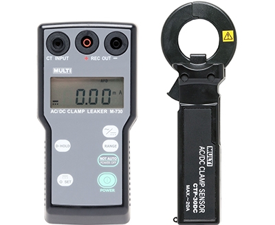
After making artificial ground fault (approx. 12mA), measurements of DC current at three places (grounding line of boosting transformer, DC current side of power conditioner and artificial ground fault point) were implemented by DC clamp tester (M-730). Consequently, the measured values of these three places were almost same, which means that all the DC ground fault current flowed out to AC current end and the current difference of P&N phase at DC current side of power conditioner was almost same as DC ground fault current.

M-600

FEATURES
- Wide application for process control and automotive service.
- The world first AC/DC leakage current clamp tester with 0.1mA resolution.
- The least influence from the external magnetic field and noise with double shielding CT.
- Memory Function for MAX. and MIN. Value.
- For measurements of 4〜20 mA current loop signal of transmission control
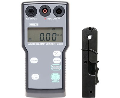
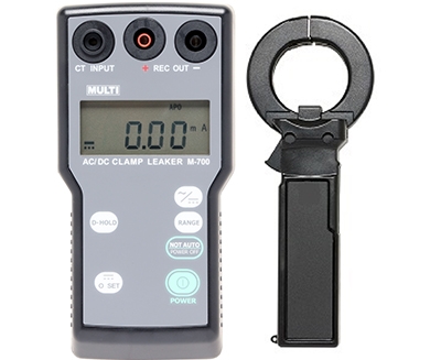
M-700

FEATURES
- The World First High Accurate AC/DC Leakage Current Testers.
- High Sensitive for Low Range Leakage Current.
- Suitable for Measurement of 4-20mA DC Controlled Circuit
- DC mV Analog Signal Output.
- Lowest Influence from Magnetization & Terrestrial Magnetism.
- Wide Measuring Ranges – up to DC 1000mA & AC 10A.
M-730

FEATURES
- The World First High Accurate AC/DC Leakage Current Testers.
- High Sensitive for Low Range Leakage Current.
- Suitable for Measurement of 4-20mA DC Controlled Circuit
- DC mV Analog Signal Output.
- Lowest Influence from Magnetization & Terrestrial Magnetism.
- Wide Measuring Ranges – up to DC 1000mA & AC 10A.
M-740

FEATURES
- The World First High Accurate AC/DC Leakage Current Testers.
- High Sensitive for Low Range Leakage Current.
- Suitable for Measurement of 4-20mA DC Controlled Circuit
- DC mV Analog Signal Output.
- Lowest Influence from Magnetization & Terrestrial Magnetism.
- Wide Measuring Ranges – up to DC 1000mA & AC 10A.
Technical Specifications
| Parameters | M600 | M700 | M730 | M740 | ||
|---|---|---|---|---|---|---|
| Measuring function | DC/AC Leakage Current (AC true RMS reading) (50/60Hz) | AC/DC Leakage Current (45Hz~65Hz) | ||||
| Range | 200mA/2000mA/10A | DC 100mA/1000mA, AC 100mA/1000mA/10A (45Hz〜65Hz) | ||||
| Resolution | 0.1mA/1mA/0.01A | 0.01mA/0.1mA/0.001A | ||||
| Accuracy | (23℃±5℃, 80%RH or less) Range/Input range/Resolution/Accuracy AC 200mA/0~1999mA/100μA/±1.0%rdg±5dgt (50/60Hz) AC 2000mA/0~199.9mA/1mA/±1.0%rdg±5dgt (50/60Hz) AC 10A/0~9.99mA/0.01A/±1.0%rdg±10dgt (50/60Hz) DC 200mA/0~199.9mA/100μA/±1.0%rdg±3dgt DC 2000mA/0~1999mA/1mA/±1.0%rdg±3dgt DC 10A/0~9.99mA/0.01A/±1.0%rdg±10dgt Error by hysteresis of hall effect :±3%rdg | DC Current (Accuracy:23℃±5℃, less than 85%RH) Range/Measuring Range/Resolution/Accuracy 100mA/0.1~±50.00mA/0.01mA/±1%rdg±5dgt 100mA/±50.01~±99.99mA/0.01mA/±1%rdg±10dgt 1000mA/1~±300mA/0.1mA/±1%rdg±10dgt 1000mA/±300.1~±700mA/0.1mA/±2%rdg±10dgt 1000mA/±700.1~±999.9mA/0.1mA/±3%rdg±10dgt AC Current (Accuracy:23℃±5℃, less than 85%RH) Range/Measuring Range/Resolution/Accuracy 100mA/0~99.99mA/0.01mA/±1%rdg±10dgt(50/60Hz) 1000mA/0~999.9mA/0.1mA/±1%rdg±10dgt(50/60Hz) 10A/0~9.999A/0.001A/±1%rdg±10dgt(50/60Hz) Max. input current : AC 20A | ||||
| Display | 3.5 digit LCD, max. reading of 1999 | Max. 2000 count on LCD with annunciator | ||||
| Jaw opening capability | 20㎜φ | 5㎜φ (CTP-05DC) | 30㎜φ (CTP-30DC) | 40㎜φ (CTP-40DC) | ||
| Safety standard | IEC 61010-1, IEC 61010-2-032 CATⅡ 300V. | IEC61010-1/61010-2-032 CATⅡ 600V or CATⅢ 300V | ||||
| Measuring method | Dual integration method with true RMS reading. | Clamp CT (CTP-05DC:Slide/Hook Type) AC current detection : Average sensing A/D conversion : Dual integration method | ||||
| Sampling | 1.6 times/s | 1 time/sec. for DC and 6 times/sec. for AC | ||||
| Over range indication | ”OL” mark on LCD | |||||
| Data hold indication | ”DH” mark on LCD | |||||
| Low battery indication | ”B” mark on LCD | |||||
| Min. memory function | "Min" mark on LCD with min. value | - | ||||
| Max. memory function | "Max" mark on LCD with max. value | - | ||||
| DC current zero offset | By push button switch | "0 ADJ" switch | ||||
| Limitation of circuit voltage | Less than AC/DC 300V | less than AC/DC 500V | ||||
| Withstanding voltage | AC 2300V/1 minute max. between the core of CT and outer case. | AC 3700V/1 minute between CT and outer case | ||||
| Operating temperature | 0℃〜50℃, < 80% RH (Non-condensing) | 0〜50℃, < 85%RH (without condensation) | ||||
| Storage temperature | -20℃〜60℃, < 75% RH (Non-condensing) | -10〜60℃, < 70%RH (without condensation) | ||||
| Power supply | 1.5V (“AA” size, UM-3)×2 | 1.5V ("AAA" size, UM-4)×4 | ||||
| Battery life | 120 hours or more (Alkaline) | Approx. 200h for continuous use | ||||
| Auto power off | The meter is set to power off mode approx. 10 minutes after the power switch on. | Approx. 10 minutes after power on (Auto power off function can be released by the switch) | ||||
| Size | 76(W)×194(H)×30(D)㎜ | Display Part 78(W)×155(H)×32(D)㎜ CT (CTP-05DC) 19(W)×133(H)×28(D)㎜ | Display Part 78(W)×155(H)×32(D)㎜ CT (CTP-30DC) 33(W)×170(H)×24(D)㎜ | Display Part 78(W)×155(H)×32(D)㎜ CT (CTP-40DC) 64(W)×162(H)×23(D)㎜ | ||
| Weight | Approx. 340g | Display: approx. 280g CT : approx. 100g | Display: approx. 280g CT : approx. 165g | Display: approx. 280g CT : approx. 130g | ||
| Accessories | Carrying case .................. 1 Instruction manual............ 1 Batteries .......................... 2 | Carrying case .................. 1 Instruction manual............ 1 Batteries .......................... 4 | ||||
| Signal Output | DC 100mV full scale to each range (output impedance: less than 10KΩ) | |||||

