LEAKY INSULATOR DETECTOR (LID)
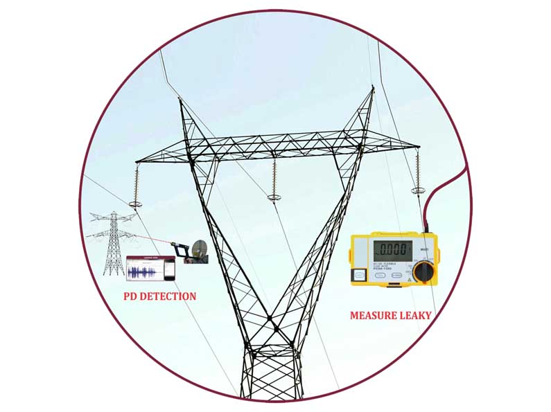
Application field: The Leaky Insulator Detector (LID) is a system which utilizes AC/DC Current sensor and Ultrasonic technology for predictive maintenance. The Leaky Insulator Detector (LID) has a Flexible clamp sensor and Ultrasound Receiver.
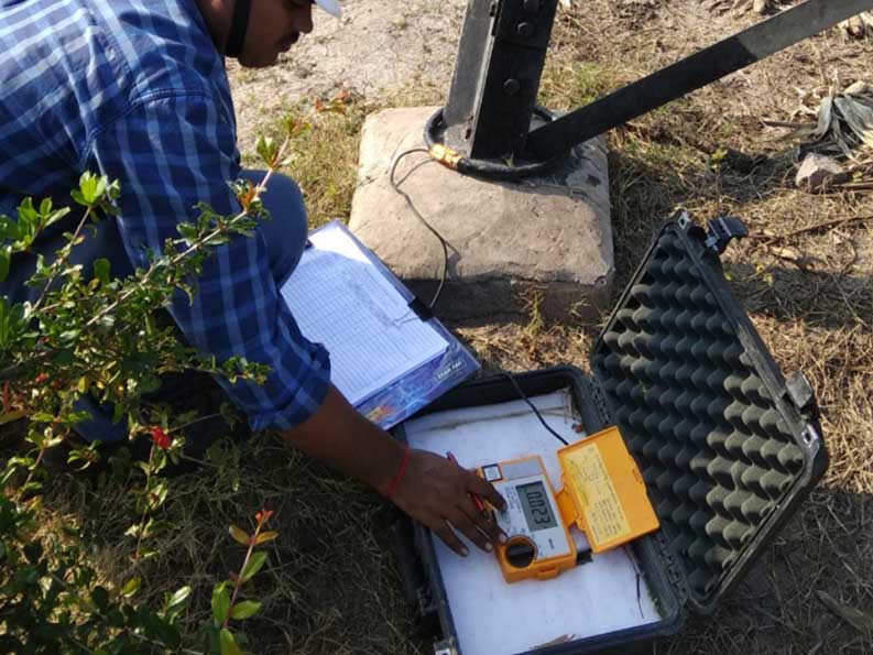
The Flexible AC/DC Clamp meter is specially designed sensor to measures the AC/DC leakage current in HVAC/HVDC Towers leg (caused due to the leaky insulator) and if the leakage current is greater than average value of nearby 10 towers, this will provide the primary information that the tested tower has leaky insulator and it is a leaky tower.
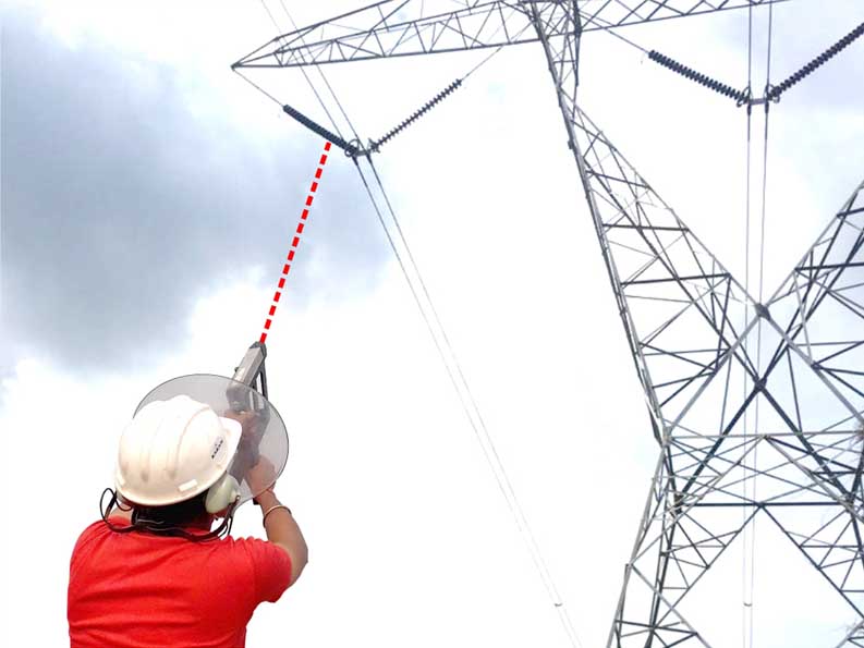
Ultrasound Receiver is based on Ultrasound Technology which picks Partial Discharge Ultrasound from a distance up to 100 meters and converts Ultrasound into audible sound with digital graph and analogue reading. After leakage current measurement, Ultrasound Receiver is used to scan the insulator strings of the leaky tower and pinpoint the phase and position of the leaky insulator.
Features
- Best Signal Sensitivity Available: As certified by NASA
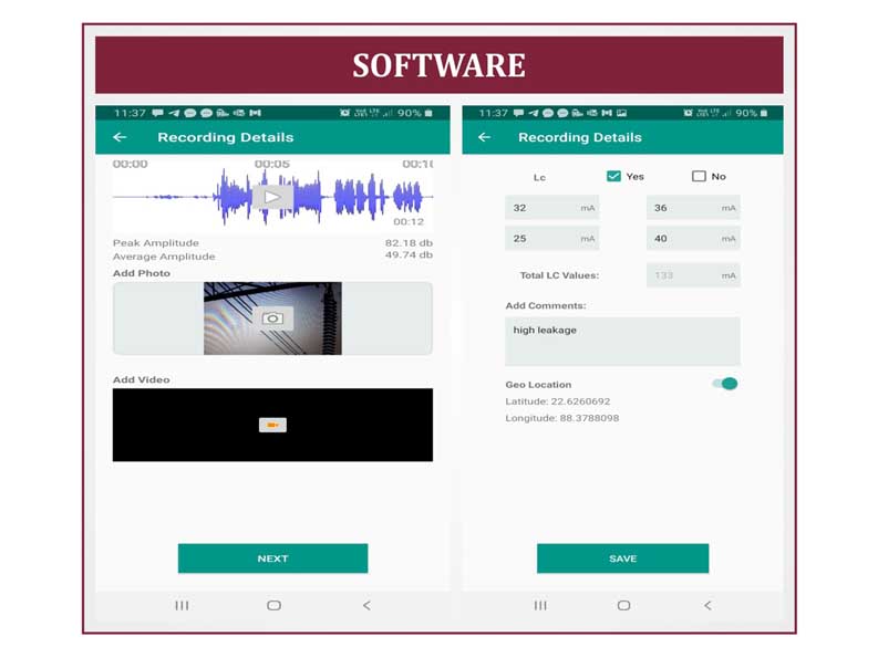
- Optional Instant: Ultrasound Data capture and Analysis.
- Leakage current: Measures both AC/DC leakage current
- Testing of Substation equipment, Distribution & Transmission lines
- Indication and location of arcing or Corona Discharge. Measures body leakage current and Geo magnetic DC current created due to unperiodic rotation of earth.
- Pinpoint faults at lightning Arrester, Bushings & Contaminated Insulator / Transformer.
- Indicate Broken Strands, Loose Hardware, Improper Installations, & Damaged / Punctured Insulator, Failure of Earthing.


Technical Specifications
- Dimensions : Dish Diameter 13” (330 mm)
- Overall : 21” x 17” x 1.26” (533 x 432 x 32 mm).
- Weight : 45 Oz (1.3 kg) (without Ultra sound receiver).
- Housing : Extruded Aluminum.
- Power Supply : Two (2) Standard AAA Alkaline Batteries (for laser) and one 9V alkaline battery (for Receiver unit)
- Battery Life : > 45 Hours.
- Sensitivity : Minimum Intensity 10-12 w/m2, Minimum ultrasonic Pressure 2.0x10⁻⁵ Pa@40 kHz.
- Distance of Reception : Up To 100 meters.
- Frequency Bandwidth : 1.8 – 2.2 kHz @ level 0.7 (or -3 dB).
- Working Resonance Frequency : 40 kHz +/- 1.5 kHz.
- Operating Temperature Range : -4° to +130° F (-20° to +54° C).
- Controls : Laser Trigger On / Off Switch.
- Facility to display result in External Digital device.
- Measuring Function : AC/DC Leakage/Line Current
- Measuring Method : Dual Integration Mode
- Measuring Range : AC/DC 3A/30A/300A/2500A (AC50/60 Hz & DC)
- Range Selection : 4 Range Manual by Rotary Switch